The tunnel diode oscillator (TDO) is a highly stable self resonating oscillator system that we use to measure rf penetration depth in conducting, superconducting, and magnetic materials. It allows us to study superconducting properties, resistivity, and magnetic properties of materials without attaching leads, an advantage with the small delicate samples that we study. In addition, working at frequencies in the tens or hundreds of megahertz is compatible with pulsed magnetic fields where we can study material properties up to 50 tesla in our own laboratory, or 100 tesla at the NHMFL at Los Alamos National Laboratory.
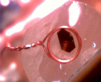
An organic superconductor sample mounted in a coil so it can be investigated via rf penetration. The coil is just under 1 mm in diameter.
As an example of how simple it is to prepare a sample for study, a picture of a sample in a coil is shown to the left. The coil is attached to a circuit diagramed below to force it to ring at its resonant frequency. As the properties of the material change, the penetration depth changes, which in turn changes the inductance and the resonant frequency of the circuit. By measuring the frequency shift of the circuit we can infer the changes in the properties of the sample.
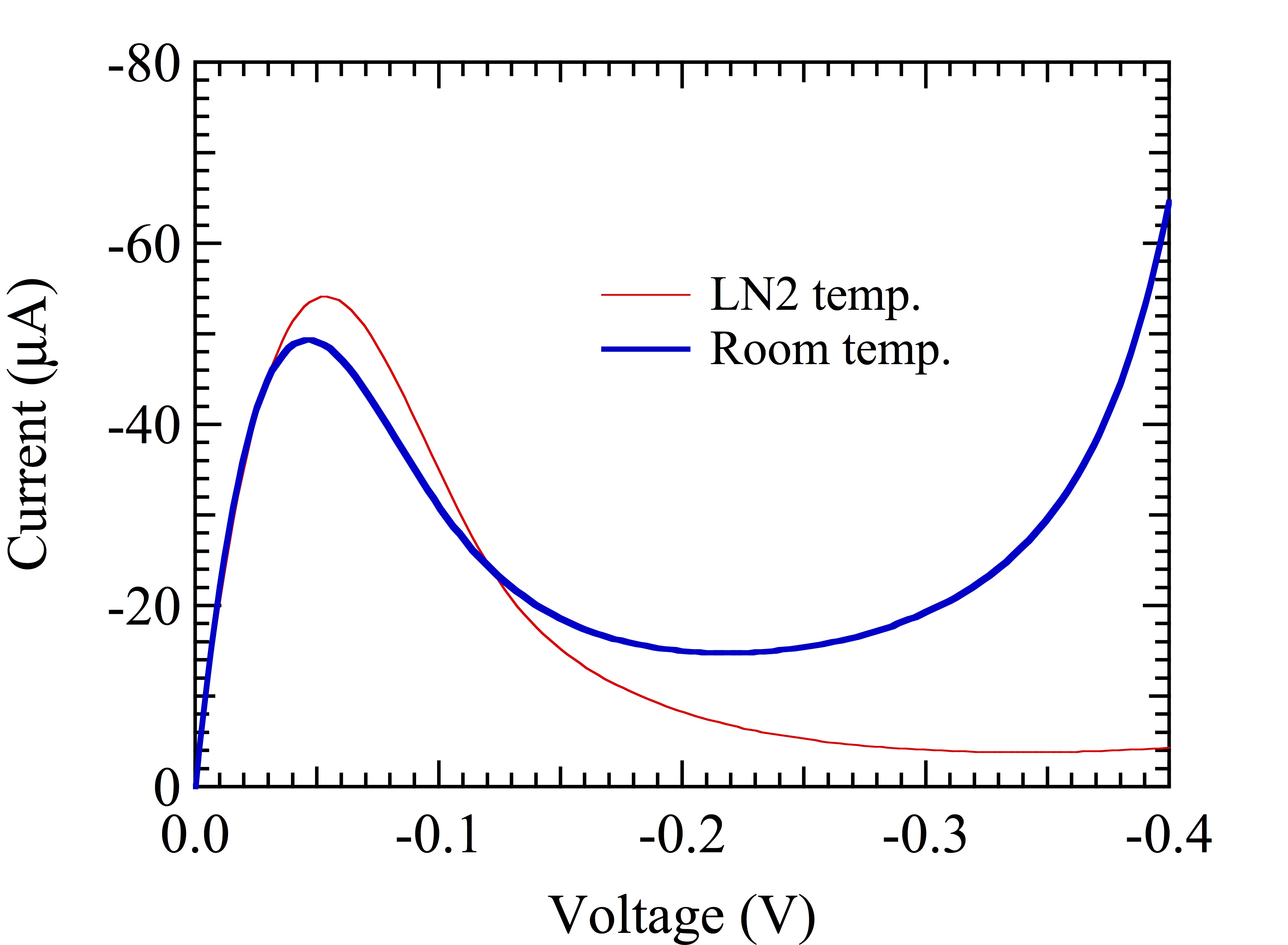
The circuit we use is based on a tunnel diode which has an area of negative resistance (decreasing current with increasing voltage) due to quantum mechanical tunneling through an insulating layer between the PN junction, as shown in the figure below. If the diode is biased into its negative resistance region it becomes unstable, and if it is connected to a resonant circuit, the circuit will self resonate. We normally run the circuit at cryogenic temperatures, and at low temperatures the circuit can have a stability of 1 part in $10_9$ in the right situation. In most cases we place our sample in the coil of the resonant circuit as shown above, and as the penetration depth into the sample changes, the inductance of the coil changes which shifts the resonant frequency. The high stability of the circuit allows us to measure changes of penetration depth less than 1 angstrom.
A tunnel diode has a region of negative resistance. This IV curve of a BD-4 tunnel diode has a peak current of 50 $\mu$A.
The seminal paper on the use of the TDO is by Van Degrift 1, and we have adapted the design principles in that paper for studying solid state samples at high magnetic fields. Our basic methods and design criteria solve the problems of using small lower Q coils, pulsed magnetic fields, and very low (dilution refrigerator) temperatures.
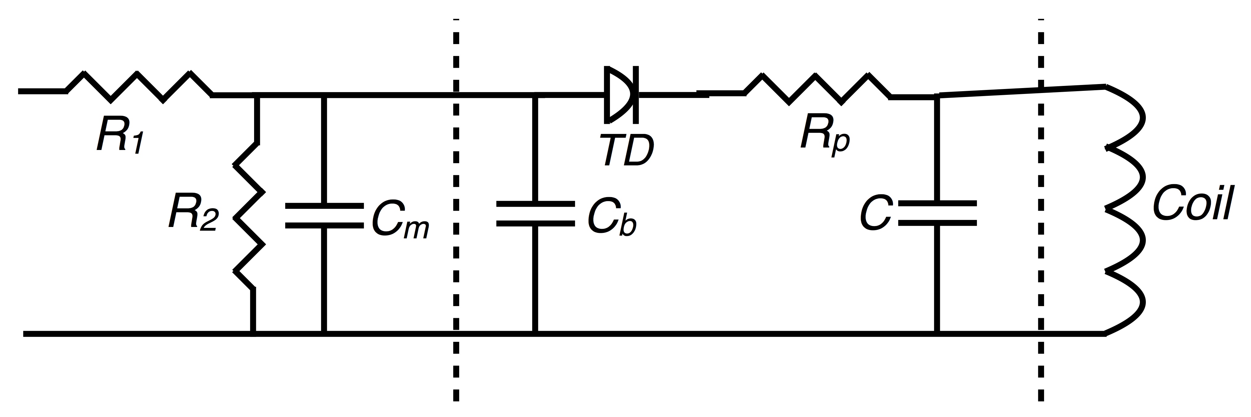
An example of a TDO circuit that we use in our research is shown is the second figure. The tunnel diodes we use have a peak current of 150 - 400 $\mu$A. The diode voltage at the peak current is always about 40 mV, and a typical 300 $\mu$A diode corresponds to a negative resistance $R_n = -300\Omega$. The parasitic resistor $R_p = 75\Omega$ based on VanDegift's formula of $R_p = R_n/4$, and $R_2 = (R_n - R_p)/4$, or about $50Ω$ in our case. $R_1$ ideally forms the rest of the voltage divider, and helps to isolate the circuit from noise from the top of the cryostat, although it also adds heat to the cryostat. In the original paper it was set to the absolute value of $R_n$, but we tend to set it equal to $R_2$, and move that resistance to the bias box outside the cryostat. Because $R_1$ is now small, $C_c$ is moot, so we skip it. $C_b$ keeps the voltage more or less constant at the top of the voltage divider, and serves to isolate the oscillator from the outside world. A typical value of $C_b$ is $1000/(2\pi f |R_n|)$ where f is the resonant frequency of the oscillator.
TDO circuit. Typical values are in the text. The dashed lines indicate where the circuit is split and connected by micro coax, or for the measurement coil, sometimes just twisted pair. In most implementations the voltage divider resistors $R_1$ and $R_2$ are separated from the rest of the circuit by at least 10 cm to avoid heating the sample, and $C_m$ helps avoid reflections in that run of coax. C is the capacitance of the resonant part of the circuit, although in our setup most of the C contribting to $\omega = 1/\sqrt{LC}$ is parasitic as explained in the text.
The inductor is the coil that we wind that will contain the sample we plan to study, as seen above. A high filling factor translates to a sensitive measurement, so we tend to wind custom coils for each sample with the goal of a 20-60% filling factor. The capacitor of the oscillator (tank circuit) is mostly from the parasitic capacitance, but we find that putting at least a 1-3 pf chip capacitor on the circuit board stabilizes the frequency against the variable diode capacitance and cable capacitance that inevitably couples to the circuit. Click here to get to a calculator for setting up a TDO based on Van Degrift's design, in addition to other design considerations.
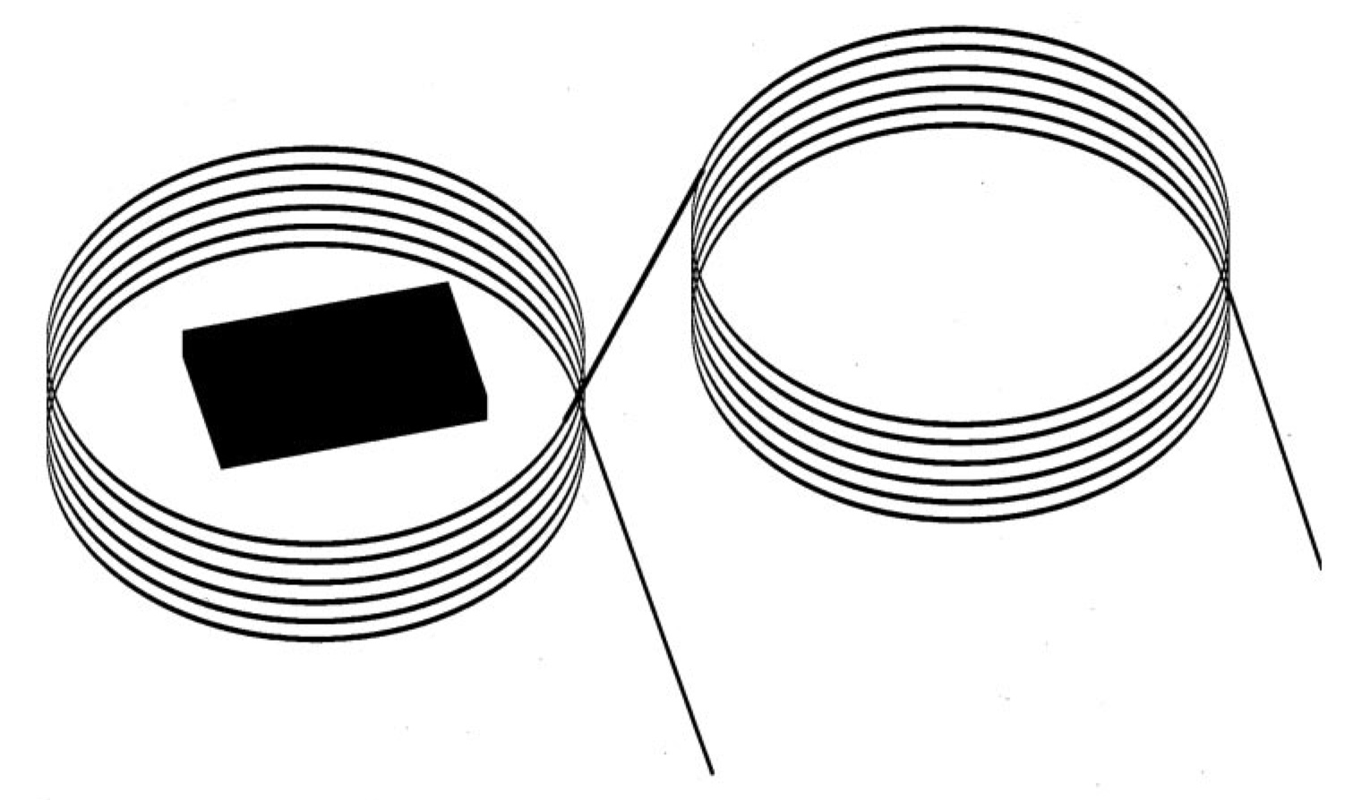
There are two important additions to the circuit critical to our work. As described in our paper 2 for pulsed fields there can be a large induced voltage coming from the coil which will push the diode off of its bias point. To avoid that problem we add a second identical coil, or any additional wire configuration, that has the equal and opposite area exposed to the changing magnetic field. This addition will cancel the induced voltage. The effective area of the coil will become larger and hence the filling factor of the sample coil system will become less, but we usually have enough signal to noise still get the data we need.
A compensated coil
A second modification to the circuit for our experiments is to move the bias resistors $R_1$ and $R_2$ to a higher point in our cryostat, 4 - 50 cm away from the rest of the circuit, to avoid heating the area where the sample is.
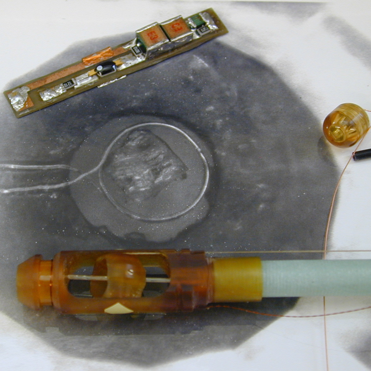
One of the advantages of the TDO penetration depth method is that the method is robust. It runs at a frequency that can be adjusted to fall in a quiet part of the spectrum, far away from the low frequency dB/dt induced voltages and switching noise in a pulsed magnetic field. It also can be arbitrarily small and the sample does not have to be isolated as in calorimetric measurements. A good example of the harsh environments where it works is in diamond anvil cells in pulsed magnetic fields. In a collaboration with Stan Tozer at the NHMFL in 2002, we placed a coil 300 µ in diameter on the face of a diamond in a plastic diamond anvil cell. We were able to run experiments up to 5 kbar in a dilution refrigerator in dc fields up 50 T at 0.5 K in a rotating sample holder.3 A picture of the setup is shown here. This setup has been developed further by Stan Tozer and his group and is now capable of achieving 20 kbar at 0.4 K in 65 T pulsed fields.
The diamond anvil cell (center right) is made of a special high strength plastic so that it can work in pulsed fields. The background black and white picture is taken through the back of the diamond and shows the sample in the 300 µ diameter coil. The TDO circuit (top, left) and the rotating probe end (bottom) are also shown. Our present TDO circuits are almost 10x smaller.
Click here to see our latest TDO boards and a calculator for setting up a TDO based on Van Degrift's design.
Click here to see a table of calculated inductance for various coil sizes from 0.2 - 1.5 mm diameter and 1-10 turns.
Click here to see a table of resonant frequencies of real coils connected to our TDO board.
Click here to calculate the resonant frequency of a particular coil and transmission line assembly.
_______________________________________________
1C. T. Van Degrift, "Tunnel diode oscillator for 0.001 ppm measurements at low temperatures," Rev. Sci. Instrum. 46, 599 (1975). 2T. Coffey, Z. Bayindir, J. F. DeCarolis, M. Bennett, G. Esper, and C. C. Agosta, "Measuring radio frequency properties of materials in pulsed magnetic fields with a tunnel diode oscillator," Rev. Sci. Instrum., 71 4600 (2000). 3C. Martin, C. C. Agosta, S.W. Tozer, H. A. Radovan, T. Kinoshota, and M. Tokumoto "Critical field and Shubnikov-de Haas oscillations of κ-(BEDT-TTF)2Cu(NCS)2 under pressure" J. Low Temp. Phys.138, 1025 (2005).