Setting up a TDO circuit
The design equations for the components in a TDO circuit were published by Van De Grift in 1970 1. We have made a live calculator, below, which uses that method to find the best components for a particular diode and resonator. In most cases the resonator in our experiments a a small coil 0.2 - 1.5 mm in diameter, or a planar spiral coil of a similar size. The starting point for picking the components for the circuit is to find the negative resistance of the tunnel diode and pick the frequency of the resonator based on the coil inductance and capacitance. For small coils the parasitic inductance and capacitance may be important to consider. For example, assume a one mm four turn coil is connected by six cm of coax (we use 1 mm coax in our cryostat) and a 1.1 pF capacitor is soldered on the board. Nominally the coil is 0.0243 $\mu$H and using the formula $\omega = 1/\sqrt{LC}$ the resonant frequency should be 973 MHz. If we test this configuration we find that the added reactance of the coax cable plus the parasitic capacitance of the coil and board will lower the resonant frequency to ~ 600 MHz.| Note | Label | Value | Units | Power | Units |
|---|---|---|---|---|---|
| Enter Above | $|R_n|$ | Ω | |||
| Enter Above | freq | MHz | |||
| $R_p$ | Ω | $\mu$W | |||
| $R_1$ | Ω | mW | |||
| $R_2$ | Ω | mW | |||
| $C_B$ | pF | ||||
| $C_C$ | pF | ||||
| Est. Peak I | $I_P$ | $\mu$A | |||
| Diode Power | $\mu$W | ||||
| Bias Bd Power | mW | ||||
| TDO Bd Power | $\mu$W |
Low temperature considerations
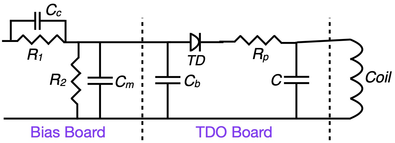
Although $R_1$ is part of the voltage divider that sets the dc bias voltage on the tunnel diode, the bias box at room temperature contains additional resistance, and the location of that resistance, at room temperature far away from the TDO circuit or close to the circuit is somewhat arbitrary. Some of it should be close to the circuit to isolate the circuit from room temperature noise, but it also could be the largest source of heat in the circuit (along with $R_2$). For these reasons we separate $R_1$ and $R_2$ on a separate board and place that bias board 5 - 15 cm away from the TDO board and sample to avoid heating the sample chamber.If $R_1$ is chosen to be smaller than about 200 $\Omega$, $C_c$ becomes unnecessary, as it was there to form a low impedance path around $R_1$.
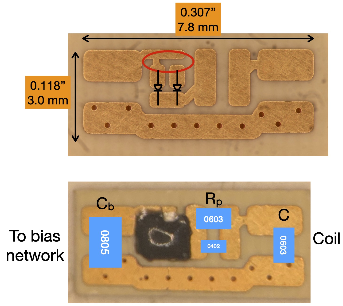
The location of the components on our small boards is shown in Fig 2. It is important to solder them on very quickly so as not to heat up the diodes, which are delicate. It is best to use solder paste so that the joints can be made in less than one or two or seconds. Luckily, once the circuit is set up, most of the reattachments are on the coil side, farther from the diodes. The default setup for the boards is both diodes are connected, one with a copper trace and the other with silver paint. Either connection can be filed open or closed again with silver paint allowing the peak current of the circuit to be adjusted to one of two or three values depending on if the diodes are the same size or different sizes. In the case that only one diode is needed at a time, the two diodes can be a sa way to double the lifetime of the circuit. In the present design the individual diodes are nominally 250 or 500 $\mu A$ peak current enabling circuit configurations with 250, 500, 750, or 1000 $\mu A$ peak currents.
Fig. 3 shows two circuits on a rotating platform on a probe designed for the dilution refrigerator in the 32 tesla all superconducting magnet at the NHMFL in Tallahassee Florida. The coils for each of the circuits are in line with the circuit connected by the twisted wire ends that formed the coil. The copper wires in the lower left lead to a rectangular RuO resistor that serves as a thermometer.
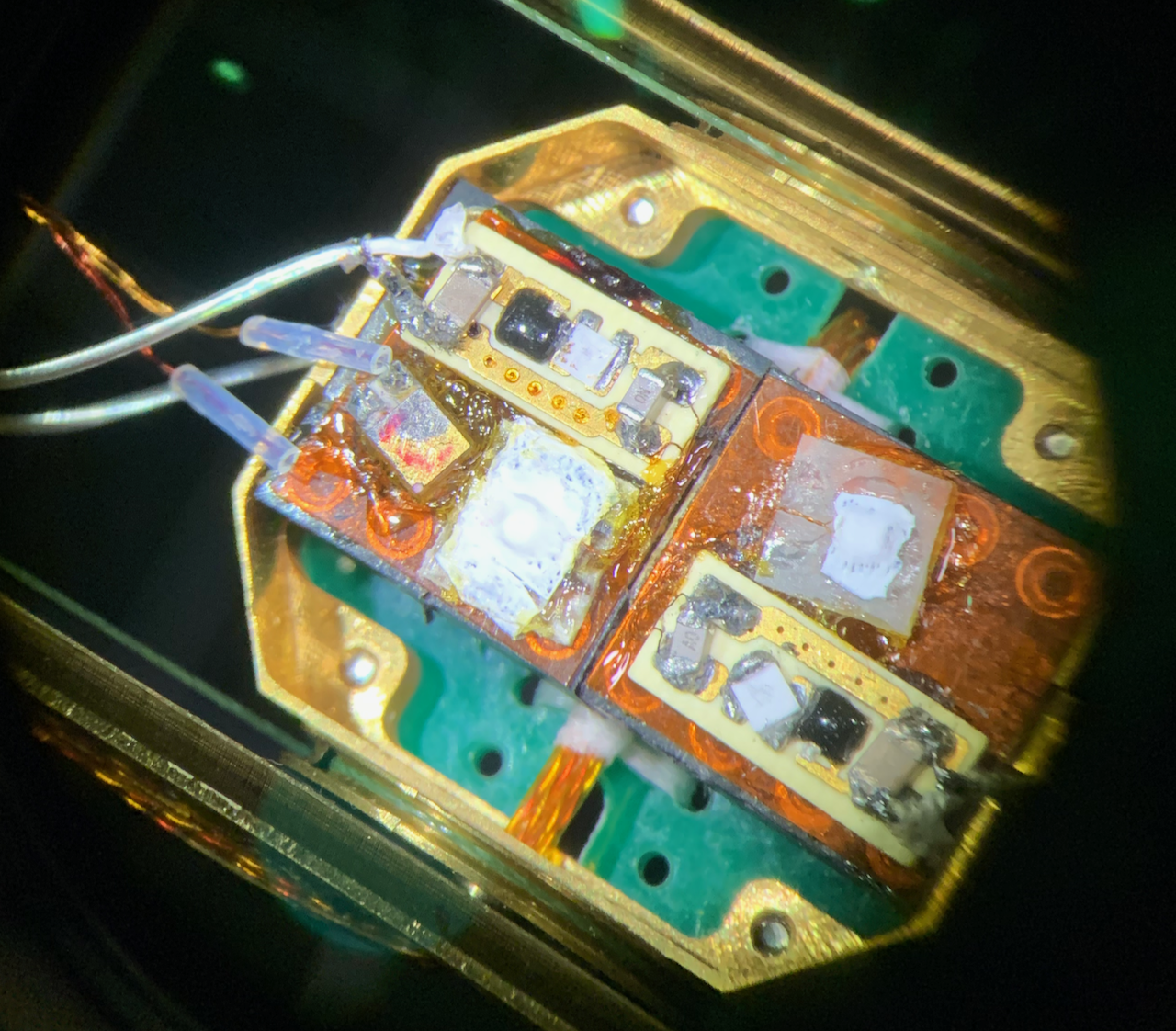
For large diodes, necessary for low Q systems such as very small coils, the diode itself will dissipate enough power to significantly raise the temperature of a dilution refrigerator. The TDO circuit could be placed far away from the coil. The compromise in that case is lowering the resonant frequency, sometimes a problem for small samples and poorer conductors if it is undesirable to have complete (saturated) penetration. In addition, a long coax and small coil will result in lower sensitivity because the sample coil is a smaller percent of the reactance in the circuit. The other problem we have encountered is that the frequency of oscillation is sensitive to the orientation of the coax between the sample coil and TDO circuit. Therefore if sample rotations are desired the system is much less noisy if the sample and TDO circuit are on the same platform, as shown in the figure.
1 C. T. VanDegrift, Rev. Sci. Instrum. 46, 599 (1975).